In this tutorial we will learn how to make bitwise operations in C. It is important to know how to set, clear and toggle a bit in C. We will make use of them a lot 🙂
Bit Operators in C
In C bit operators are “&”, “|”, “~”, “^”, “>>”, “<<“.
AND Operator
“&” A.K.A. AND operation is a bit operator in C that evaluates to TRUE if all of its operands are true and FALSE otherwise.
OR Operator
“|” OR operator is a bit operator that returns a value of TRUE if either or both of its operands is TRUE.
NOT Operator
“~” NOT operator is a bit operator that returns TRUE if its operand is FALSE, and FALSE if its operand is TRUE.
XOR Operator
“^” XOR operator is that returns a value of TRUE only if just one of its operands is TRUE.
Left and Right Shift Operators
“<<” Left Shift operator is used to move values in given number. For example;
0x20 << 2 is 0x80
0x20 = 0b0010 0000
0x80 = 0b1000 0000
as you can see al the bits are shifted two times to the left. Its same in Right Shift but reverse the order.
Set a Bit
We are using OR operator to set a bit.
a = a | (1<<k) or a |= 1<<k
The above syntax means make kth bit of a TRUE, for example;
a = a | (1<<5)
We can simply use a = 0x20; but this will make all bits zero except 5th bit. If you don’t know what is a initially, do not use it, use bitwise operations instead.
Clear a Bit
We are using AND operator to reset a bit.
a = a & ~(1<<k) or a &= ~(1<<k)
The above syntax means; make kth bit of a FALSE, for example;
a = a & ~(1<<5)
Again we can simply use a = 0xDF; but this will make all bits one except 5th bit. If you don’t know what is a initially, do not use it, use bitwise operations instead.
Toggle a Bit
We are using XOR operator to toggle a bit. Toggling simply is changing state of the bit; if it’s TRUE make FALSE vice versa.
a = a ^ (1<<k) or a ^= 1<<k
The above syntax means; toggle kth bit of a, for example;
In this tutorial we are going to create new project in KEIL uVision IDE. This tutorial will be followed all of the upcoming tutorials otherwise stated. So, let’s start 🙂
A Fresh Start
Once you double-click uVision IDE, you will be faced with wide empty starting page, don’t worry we will fill that workspace throughout our journey.
Empty spaces what are we looking for?
Then follow this; Project > New uVision Project, then on the folder selection; create new folder in Documents and name it uVisionWorkspace. This will be our main folder for all projects. Then create another folder in uVisionWorkspace and name it according to your desired project name. Don’t use space between words, use “_” or “-” instead. For example “Example_Project”.
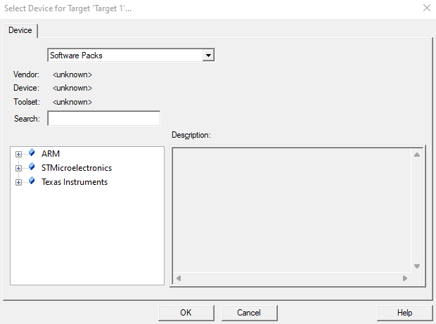
When you named your project and click OK. Pop-up window below will appear.
Target selector window.
Enter “411RE” to search textbox than highlight the MCU. If you use another MCU search accordingly. Then click OK.
After MCU selection, another po-up window will appear. It’s the Run Time Environment selection window. We will not use any of high-level library as I promised. Only we need Cortex-M core library and startup files for given MCU. These are required because we are not going to make startup file from scratch in this tutorial it will maybe be another topic of tutorial series.
Run-Time Environment selection window.
After configurations project will be ready to use. My personal preference I will rename “Target 1” folder as “F411RE” and “Source group” as “src”.
I am addicted to smell of freshly created project 🙂
Now we need to configure options for target. This is important step! Do not skip. For this right-click target name (e.g. F411RE folder). Then click “Options for Target ‘F411RE’…”.
Target options window.
These are briefly explanations which tab is for, we will not use many of them but it’s good to know.
“Device” tab let’s you to check your selected device settings and Toolset.
“Target” tab allows you to configure the device and to set application-specific options. The fields and options displayed in the dialog depend on the device selected.
“Output” tab allows you to configure the files that will be created automatically when you compile the code.
“Listing” tab allows you to configure which listing will be done. µVision creates several listing files that can be configured with these dialogs.
“User” tab allows you to specify programs that are executed during the build process. Programs can be run before compiling, before building, and after building the application.
“C/C++(AC6)” tab is Options dialog for ARM Compiler 6.
“Asm” tab is Options dialog for Arm Assembler.
“Linker” tab is options for Arm Linker.
“Debug” tab defines options that are applied when a debugging session is started.
“Utilities” tab configures the options for programming the Flash memory of the target system.
Configuring Target Options
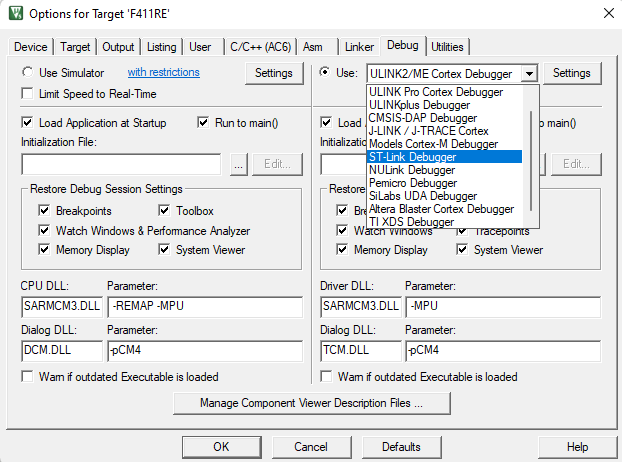
We will configure “Debug” tab for just simplicity. Other options are default will be fine.
Once you open “Debug” tab; change debugger as ST-Link Debugger than click Settings button after.
Debugger selection.
On the settings window click “Trace” tab and check enable trace box. Then “Flash Download” tab check reset and run box.
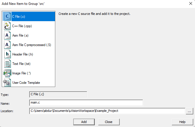
Creating main.c File
Last object is creating main.c file for codding. For this; right-click “src” folder then click “Add New Item to Group” then choose C File name it main.c then click OK.
main.c file will open. The below structure will be used every single project.
#include "stm32f411xe.h"

int main()
{


	while(1)
	{


	}
}
Good job if you make it through here 🙂 I hope I will see you in next tutorial.
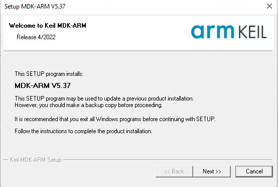
First step is to go KEIL website. When you reach the download section of the site, It will ask some questions, you have to fill those questions with your personal information. After that you will see MDKxxx.exe. After you click, download will start, once you finished downloading install the IDE as standard as you install any software.
Popup window for MDK537.exe
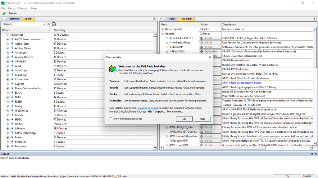
When installation is start it will automatically setup all necessary drivers. Once the installation is finished Pack Installer window will appear.
Pack Installer window.
Inside the Devices tab, search F411RE. If you are using another board for development search according tot your board specifications.
Searching MCU.
Once you select the right MCU install (it’s already installed on my computer) icon will appear in packs window. Wait until installation is done. Then close the window.
uVision IDE is installed and you are ready to move next step. Well done!
This series of tutorials we will learn how to write register based embedded system code in KEIL uVision for STM32 microcontrollers. This tutorial series intended to hobbyist, students, beginners and enthusiasts who want to learn embedded systems.
Hardware
I will be using STM32Nucleo-F411RE development board for all of the tutorials, but it is not necessary to have exactly same board. I will try to cover how to follow datasheet, reference manual etc. For now, if you have any Nucleo or Discovery series development board its nice to begin with.
If you are in a tight budget you can use one of the clone or even a Chinese boards.
Maybe we will design a development board from scratch in another series 🙂
Software
All of the tutorial series I will be using Keil uVision IDE for development environment. uVision supports all silicon vendors with more than 9.500 devices. Its an essential tool for programming and debugging. The bright side is it is free to use 🙂